
To size a borehole pump, first establish the flow your application needs, calculate total dynamic head at that flow, and confirm that the borehole can support the proposed pumping rate and schedule. Then check the exact pump curve, physical fit, motor and controls.
The result should be a requirement such as “1.0 m³/h at 47 m total dynamic head, within the borehole test recommendations.” Borehole depth or motor kW alone cannot tell you how much water a pump will deliver.
This guide covers clean-water supply to an open storage tank or directly to a pressure system. It explains what to measure, shows a worked example and provides a selection request you can copy for a supplier.
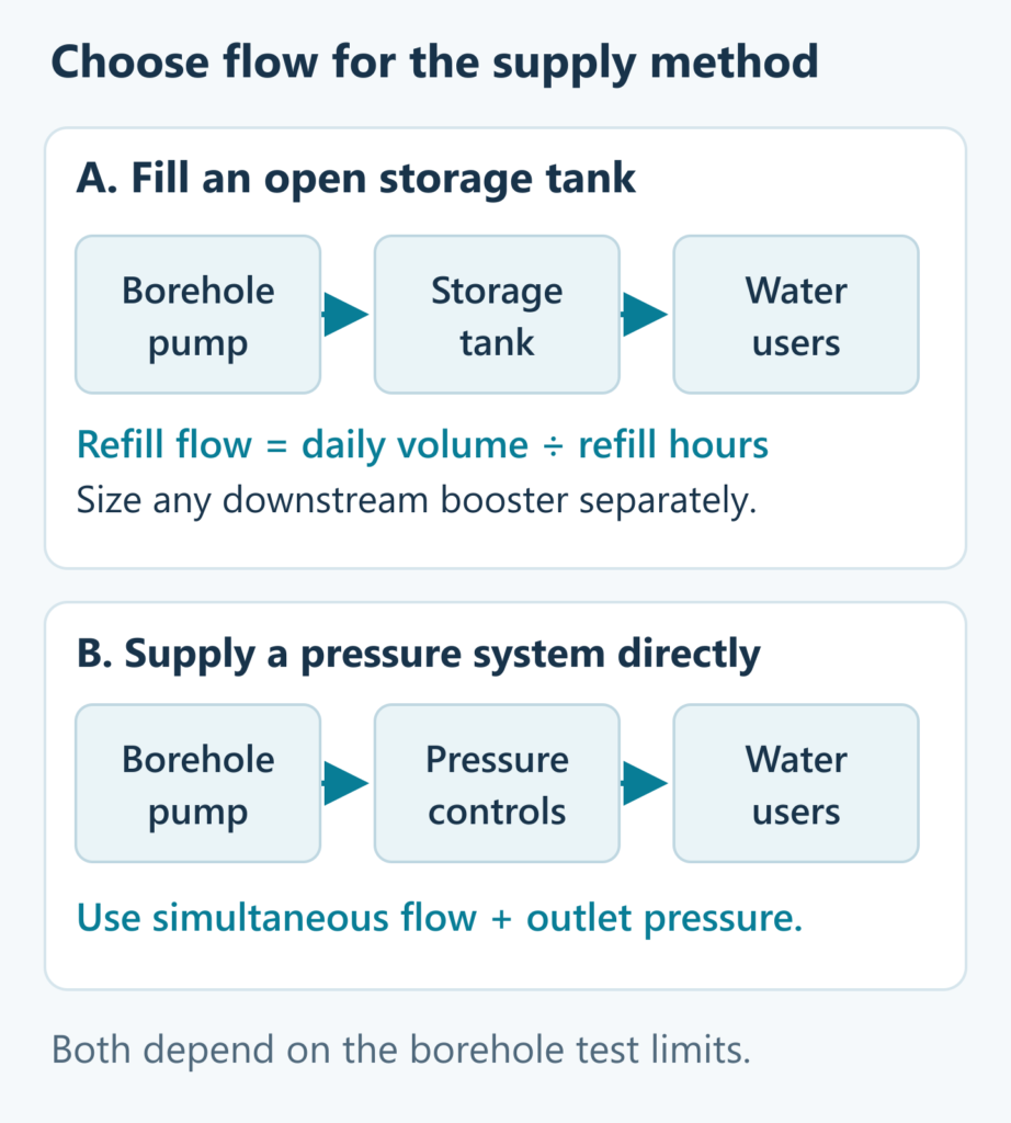
1. Decide whether the pump fills a tank or supplies demand directly
These two arrangements need different flow inputs.
Filling an open storage tank
Start with daily water use and the time available for refilling:
Minimum average refill flow = daily water requirement ÷ available pumping hours.
For 3,000 L/day, or 3 m³/day, with four available pumping hours, the minimum average flow is 0.75 m³/h.
The tank can supply short periods of high demand while the borehole refills more slowly. Where a downstream booster is needed, size it separately for the flow and pressure required at the taps or irrigation outlets. Storage does not increase the water the borehole can sustainably provide.
Supplying taps or irrigation directly
Use the flow and pressure required by the loads that may run together. Daily water use alone does not tell you whether the pump can support simultaneous taps or an irrigation zone.
For irrigation, use the zone layout and emitter requirements. For a house, have simultaneous demand assessed for the proposed installation. Grundfos’ groundwater sizing guidance also starts from the required flow and pressure.
An open storage tank and a pressure tank have different jobs. A pressure tank’s usable drawdown volume helps manage pressure and pump cycling; it is not equivalent to a day’s stored water supply.
Keep units consistent: 1 m³/h = 1,000 L/h ≈ 16.7 L/min. If a test uses L/s, 1 L/s = 3.6 m³/h.
2. Collect the measurements that determine pump size
Use the drilling record, pump-test report and a sketch of the pipe route. Keep drilled depth, pump setting depth and water levels as separate measurements.
| Input | What to provide |
|---|---|
| Water demand | Daily volume; simultaneous flow and pressure for direct supply |
| Borehole test | Recommended pumping rate, daily volume or operating schedule, test date and recovery observations |
| Pumping water level | Depth below the wellhead while pumping at the proposed flow; relevant seasonal conditions |
| Other depths | Static water level, total drilled depth and proposed pump setting, each labelled separately |
| Delivery point | Elevation relative to the same reference and pressure needed at the outlet |
| Pipe route | Actual length, internal diameter, material, fittings, valves and restrictions |
| Physical fit | Actual casing internal diameter and the complete pump assembly’s largest outside dimension |
| Water conditions | Sand or other water-quality information relevant to the equipment |
| Electrical supply | Voltage, phase, frequency, motor type, cable length and proposed controller |
If the pumping water level or test recommendation is missing, obtain an appropriate assessment before accepting a final selection. A 60 m drilled depth cannot substitute for either.
3. Check the flow and pumping schedule against borehole yield
The borehole test recommendation constrains pump selection. A short test’s highest measured flow is not automatically available all year.
Check the recommended rate, operating duration and daily abstraction together. Water-level behaviour and recovery matter, especially where demand varies or seasonal conditions change. South Africa’s Water Research Commission guidance explains the role of flow, drawdown and recovery observations in borehole assessment.
If the required flow or daily volume exceeds the recommendation, discuss storage, a longer permitted refill window or demand management with the person assessing the borehole. A larger pump does not create a larger water source.
Also check the proposed pump under the lowest expected system head, when it may deliver more flow. Meeting the design point is insufficient if another expected condition lets the pump exceed the recommended abstraction rate or equipment limits.
4. Calculate total dynamic head at the chosen flow
Total dynamic head, or TDH, is the head needed to deliver the selected flow. For the arrangement considered here:
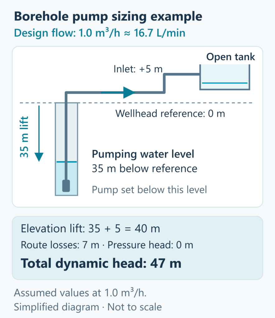
TDH = elevation lift + required outlet pressure head + pipe and fitting losses.
- Elevation lift: from the pumping water level to the delivery point.
- Pressure head: the residual pressure required at that point, converted to metres of water.
- Losses: friction through the actual pipe route, fittings, valves and other restrictions at the chosen flow.
These components follow the elevation, pipe-loss and outlet-pressure approach in the Grundfos SP-G sizing booklet.
For water, 1 bar ≈ 10.2 m of pressure head. An open tank inlet discharging freely has no additional residual-pressure requirement at that inlet; a pressurised connection may have one. The pressure-to-head relationship is explained in Grundfos’ pump-curve guide.
Use the same elevation reference throughout. Water at 35 m below the wellhead and a tank inlet at 5 m above it gives 40 m of elevation lift.
Pump setting depth is an installation input. It affects actual pipe length and equipment conditions, but does not replace pumping water level in the elevation calculation. If you change flow, recheck the operating water level and recalculate losses; do not simply reuse the previous TDH or add an arbitrary percentage.
Worked example: 3,000 litres per day to an open tank
The figures below are illustrative assumptions, not a QDD installation or product rating.
| Item | Assumed value |
|---|---|
| Daily water requirement | 3,000 L, or 3 m³ |
| Available pumping window | 4 hours per day |
| Minimum average refill flow | 3 ÷ 4 = 0.75 m³/h |
| Chosen refill target | 3 hours |
| Design flow | 3 ÷ 3 = 1.0 m³/h, approximately 16.7 L/min |
| Pumping level at that flow | 35 m below the wellhead |
| Open tank inlet | 5 m above the same reference |
| Complete route losses at that flow | 7 m, assumed rather than calculated here |
| Additional pressure at the free-discharge inlet | 0 m |
TDH = 35 + 5 + 7 + 0 = 47 m.
The selection requirement is 1.0 m³/h at 47 m TDH. At that delivered flow, refilling 3 m³ takes approximately three hours, within the four-hour window. Assume the borehole assessment permits this rate, daily volume and three-hour run.
Both the 35 m pumping level and 7 m loss must correspond to 1.0 m³/h. The example does not establish a pump model or motor power.
To see why outlet pressure matters, change the delivery requirement to a pressurised connection needing 2 bar. If elevation, operating water level and route losses remain the same, TDH becomes approximately 47 + 20.4 = 67.4 m. This is a comparison of requirements, not a reason to add pressure to an open tank or a recommendation for a particular pump.
5. Verify the duty on the exact pump curve
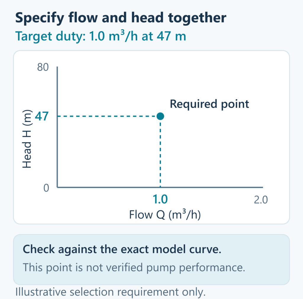
Ask the supplier to mark the required flow and TDH on the performance curve for the exact model, configuration and operating speed. For the example, the target is 1.0 m³/h at 47 m.
Maximum head and maximum flow are different ends of a curve. A pump advertised with both figures does not deliver maximum flow at maximum head. Motor kW is also insufficient: different pump hydraulics can produce different flow/head combinations with the same motor rating.
For a fixed-speed pump, the operating point is where the pump curve meets the system requirement curve. Variable-speed equipment can change its curve within its limits. Grundfos’ curve-reading lesson explains the basic intersection.
The target in the illustration is a requirement, not a measured QDD performance point. Have the supplier verify the permitted operating range, motor loading and behaviour across expected water levels and delivery conditions.
6. Confirm fit, installation and electrical compatibility
Compare actual casing internal diameter with the largest outside dimension of the complete pump, including cable guards and connectors. A nominal “4-inch” description is not a complete clearance check.
Check pump setting, submergence, water-entry conditions and motor cooling against the borehole record and corresponding equipment instructions. Do not apply a universal distance from the bottom or assume every installation needs the same cooling arrangement.
For the electrical package, confirm voltage, phase, frequency, motor type, starting or drive method, cable length and protection. Check the exact motor/controller combination, particularly for permanent-magnet motors and variable-speed drives. Franklin Electric’s AIM manuals provide equipment-specific installation and electrical guidance.
For solar pumping, daily delivery also depends on solar resource and the matched system over the day. Rated AC motor kW alone does not establish solar daily water output.
A selection request you can send to a supplier
Copy this list and fill in the available information. Mark uncertain fields as “to be confirmed” instead of guessing.
- Application: open tank filling / direct pressure supply.
- Water demand: ___ L/day; simultaneous demand ___ L/min at ___ bar, where applicable.
- Available pumping window: ___ hours/day; preferred refill time ___, if using storage.
- Required duty: ___ m³/h at ___ m TDH; attach the calculation and assumptions.
- Borehole assessment: recommended pumping rate ___; permitted schedule or daily volume ___; test date ___.
- Pumping water level: ___ m below wellhead at a tested flow of ___; seasonal allowance or condition ___.
- Delivery point: ___ m above/below the same reference; required outlet pressure ___.
- Pipe route: length ___; internal diameter ___; material ___; fittings, valves and restrictions ___.
- Installation: casing internal diameter ___; proposed pump setting ___; relevant sand/water information ___.
- Power and controls: voltage ___; phase ___; frequency ___; motor type ___; cable length ___; controller ___.
- Please confirm: exact model and curve, expected duty and operating range, motor/control compatibility, and included equipment.
Keep the inputs consistent when comparing quotations. Review QDD’s borehole pump range and pump-selection information, or send the available details for a selection enquiry.
Common sizing questions
What size pump do I need for a 60 m borehole?
The drilled depth does not define the duty. Supply the required flow, pumping water level, delivery elevation and pressure, route losses and borehole test recommendation. Then check physical fit and power compatibility.
Can I choose a pump from its kW rating?
Use flow and TDH to assess the exact pump curve first. Then confirm the motor and electrical package. A kW rating without the matching hydraulic curve does not establish delivered flow or pressure.